About a year ago I published an article on Gamasutra called Practical techniques for ray tracing in games which explained how developers can implement a series of hybrid rendering techniques on PowerVR GR6500 (our ray tracing-capable GPU) to achieve some pretty impressive effects.
Even though the target applications for ray tracing are extremely varied, this post is focused mainly on shadows. Not only does ray tracing create more accurate shadows that are free from the artifacts of shadow maps, but ray traced shadows are also up to twice as efficient; they can be generated at comparable or better quality in half the GPU cycles and with half the memory traffic (more on that later).
In what follows below, I’d like to take you through the process of implementing an efficient technique for soft shadows.
Cascaded shadow maps in traditional rasterized graphics
Firstly, let’s review cascaded shadow maps – the state of the art technique used today to generate shadows for rasterized graphics. The idea behind cascaded shadow maps is to take the view frustum, divide it up in a number of regions based on distance from the viewpoint, and render a shadow map for each region. This will offer variable resolution for shadow maps: the objects that are closer to the camera will get higher resolution, while the objects that fall off into the distance will get lower resolution per unit area.
In the diagram below, we can see an example of several objects in a scene. Each shadow map is rendered, one after another, and each covers an increasingly larger portion of the scene. Since all of the shadow maps have the same resolution, the density of shadow map pixels goes down as we move away from the viewpoint.
Finally, when rendering the objects again in the final scene using the camera’s perspective, we select the appropriate shadow maps based on each object’s distance from the viewpoint, and interpolate between those shadow maps to determine if the final pixel is lit or in shadow.
All of this complexity serves one purpose: to reduce the occurrence of resolution artifacts caused by a shadow map being too coarse. This works because an object further away from the viewpoint will occupy less space on the screen and therefore less shadow detail is needed. And it works nicely – although the cost in GPU cycles and memory traffic is significant.
Enter ray traced shadows
Ray traced shadows fundamentally operate in screen space. For that reason, there is no need to align a shadow map’s resolution to the screen resolution; the resolution problem just doesn’t exist.
The basic ray traced shadow algorithm works like this: for every point on a visible surface, we shoot one ray directly toward the light. If the ray reaches the light, then that surface is lit and we use a traditional lighting routine. If the ray hits anything before it reaches the light, then that ray is discarded because that surface is in shadow. This technique produces crisp, hard shadows like the ones we might see on a perfectly cloudless day.
However, most shadows in the real world have a gradual transition between lighter and darker areas – this soft edge is called a penumbra. Penumbras are caused by different factors related to the physics of light; even though most games model light sources as a dimensionless point source, in reality light sources have a surface. This surface area is what causes the shadow softness. Within the penumbra region, part of the light is blocked by an occluding object, but the remaining light has a clear path. This is the reason you see areas that are not fully in light and not fully in shadow either.
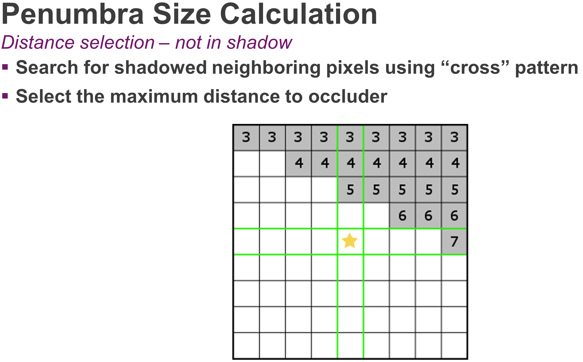
The diagram below shows how we can calculate the size of a penumbra based on three variables: the size of the light source (R), the distance to the light source (L), and the distance between the occluder and the surface on which the shadow is cast (O). By moving the occluder closer to the surface, the penumbra is going to shrink.
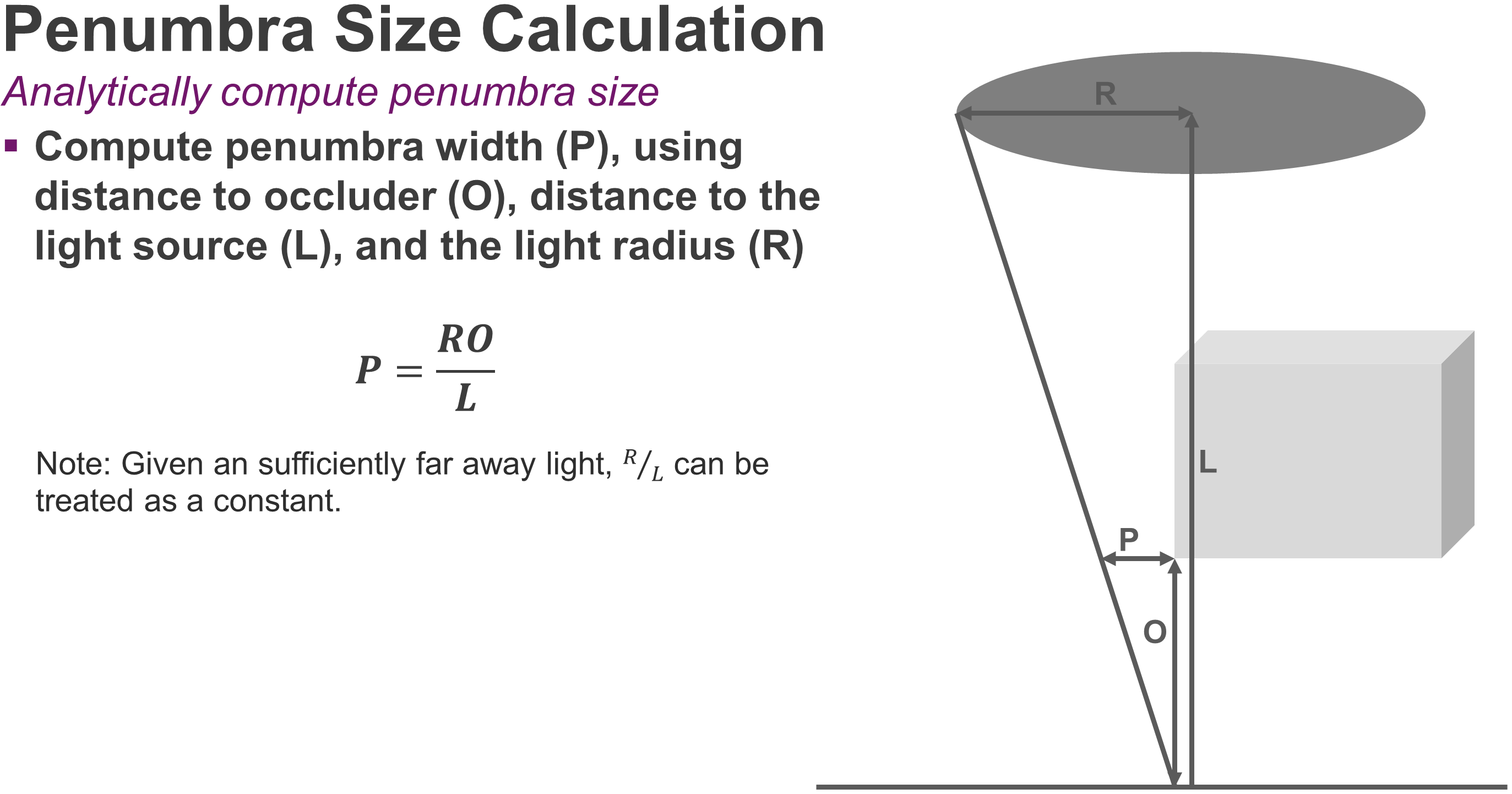
Based on these variables, we derive a simple formula for calculating the size of the penumbra.
Using this straightforward relationship, we can formulate an algorithm to render accurate soft shadows using only one ray per pixel. We start with the hard shadows algorithm above; but when a ray intersects an object, we record the distance from the surface to that object in a screen-space buffer.

This algorithm can be extended to support semi-transparent surfaces. For example, when we intersect a surface, we can also record whether it is transparent; if the surface is transparent, we choose to continue the ray through the surface, noting its alpha value in a separate density buffer.

This method has several advantages over cascaded shadow maps or other common techniques:
- There are no shadow map resolution issues since it is all based in screen space
- There are no banding, noise or buzzing effects due to sampling errors
- There are no biasing problems (sometimes called Peter-Panning) since you are shooting rays directly off geometry and therefore getting perfect contact between the shadow and the casting object
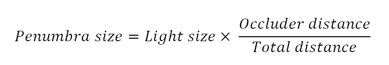
Below we show an example of the buffers that are generated by the ray tracing pass.
First, we have the ray tracing density buffer. Most of the objects in the scene are opaque, therefore we have a shadow density of 1. However, the fence region contains multiple pixels that have values between 0 and 1.
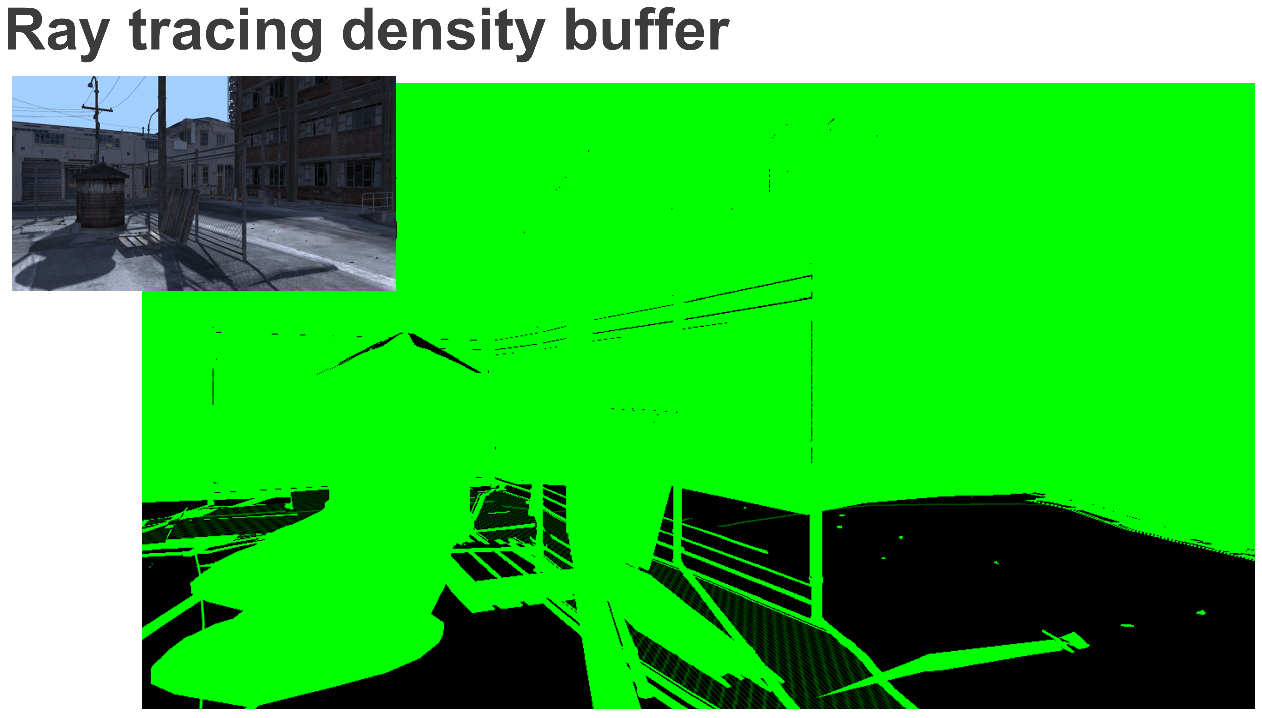
Next up is the distance to occluder buffer. As we get further away from the occluding objects, the value of the red component increases, representing a greater distance between the shadow pixel and the occluder.
Finally we run a filter pass to calculate the shadow value for each pixel using these two buffers.
Firstly, we work out the size of the penumbra affecting each pixel, use that penumbra to choose a blur kernel radius, and then blur the screen-space shadow density buffer accordingly. For a pixel that has a populated value in the distance to occluder buffer, calculating the penumbra is easy. Since we have the distance to the occluder, we just need to project that value from world space into screen space, and use the projected penumbra to select a blur kernel radius.

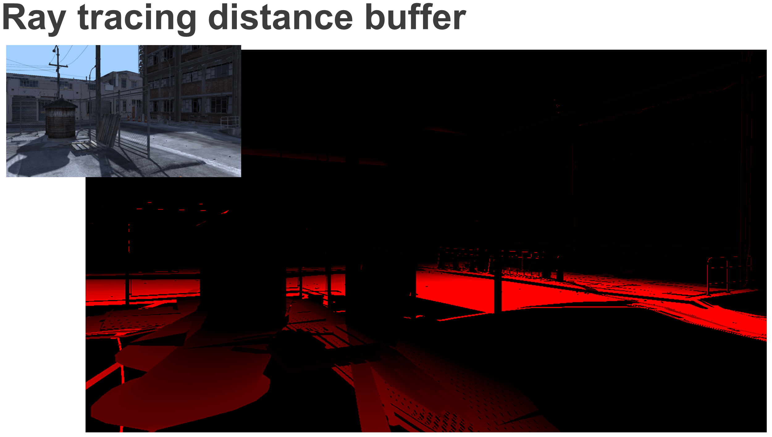
When the pixel is lit, we need to work a little harder. We use a cross search algorithm to locate another pixel with a ray that contributes to the penumbra. If we find any pixels on the X or Y axis that are in shadow (i.e. have valid distance values), we’ll pick the maximum distance to occluder value and use it to calculate the penumbra region for this pixel; we then adjust for the distance of the located pixel and calculate the penumbra side.
From here on, the algorithm is the same: we take the size of the penumbra from world space and project it into screen space, then we figure out the region of pixels that penumbra covers, and finally perform a blur. In the case where no shadowed pixel is found, we assume our pixel is fully lit.
Below we have a diagram representing our final filter kernel.
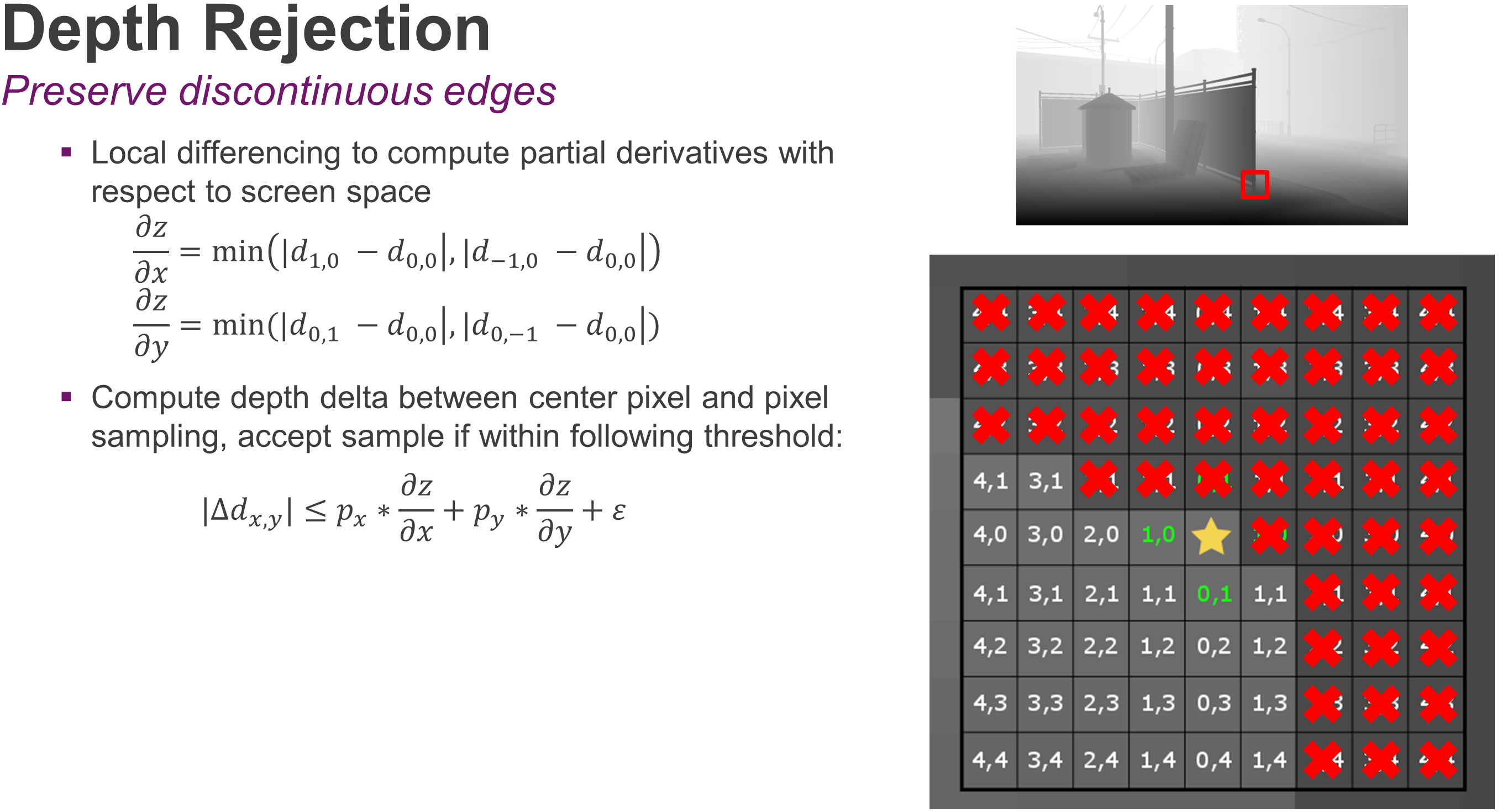
We are covering the penumbra region with a box filter and sample it while still being aware of discontinuous surfaces. This is where depth rejection comes to our aid; to calculate the depth rejection values, we use a local differencing to figure out the delta between the current pixel and certain values on the X and Y axis. The result will tell us how far we need to step back as we travel in screen space. As we’re sampling our kernel, we’ll expand the depth threshold based on how far away we are from the center pixel.
The results: cascaded shadow maps vs. ray traced shadows
In the example above, we have rejected all the samples marked in red because the corresponding area belongs to the fence and we are interested in sampling a spot on the ground. After the blurring pass, the resulting buffer represents an accurate estimate of the shadow density across the screen.
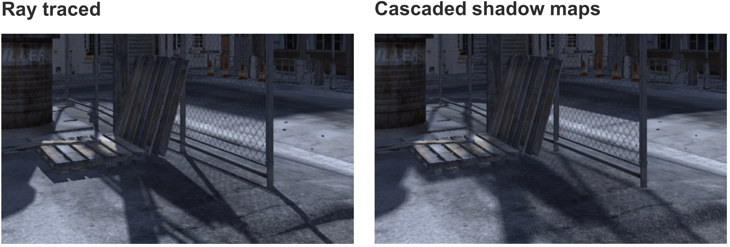
Here are the final screenshots of the original frame posted above in a side by side comparison; notice the image quality improvements achieved by ray traced shadows over cascaded shadow maps:
 Click on the image for the corresponding hi-res version
Tune in later this week for the complete set of results and further efficiency analysis.
Make sure you follow us on Twitter (@ImaginationTech) to get the latest news and announcements for the PowerVR ecosystem.
A big thank you to Justin DeCell for his huge contribution on developing the analytical soft shadows technique and for his help in making this happen.